
Car Throttle Position Sensor Diagnostics & Replacement in Daytona Beach, FL
The throttle position sensor tells the engine computer how far the throttle plate is open. That information helps the powertrain control module determine driver demand, engine load, acceleration, deceleration, fuel delivery, ignition timing, transmission behavior, and electronic throttle-control strategy.
When the throttle position sensor develops an electrical dead spot, sends an implausible voltage, loses its reference or ground, becomes intermittent, or no longer agrees with the expected throttle angle, the vehicle may hesitate, surge, idle poorly, lose power, respond erratically to the accelerator, enter reduced-power mode, or turn on the check-engine or electronic-throttle-control warning light.
Jimmy’s Mobile Care provides car throttle position sensor diagnostics and replacement in Daytona Beach, FL. We test throttle-position signals, reference voltage, ground, signal continuity, closed- and open-throttle response, sensor correlation, wiring, and related throttle-control data before recommending replacement so a throttle-body actuator fault, accelerator-pedal sensor problem, vacuum leak, MAF or MAP sensor issue, wiring fault, or PCM problem is not mistaken for a bad TPS.
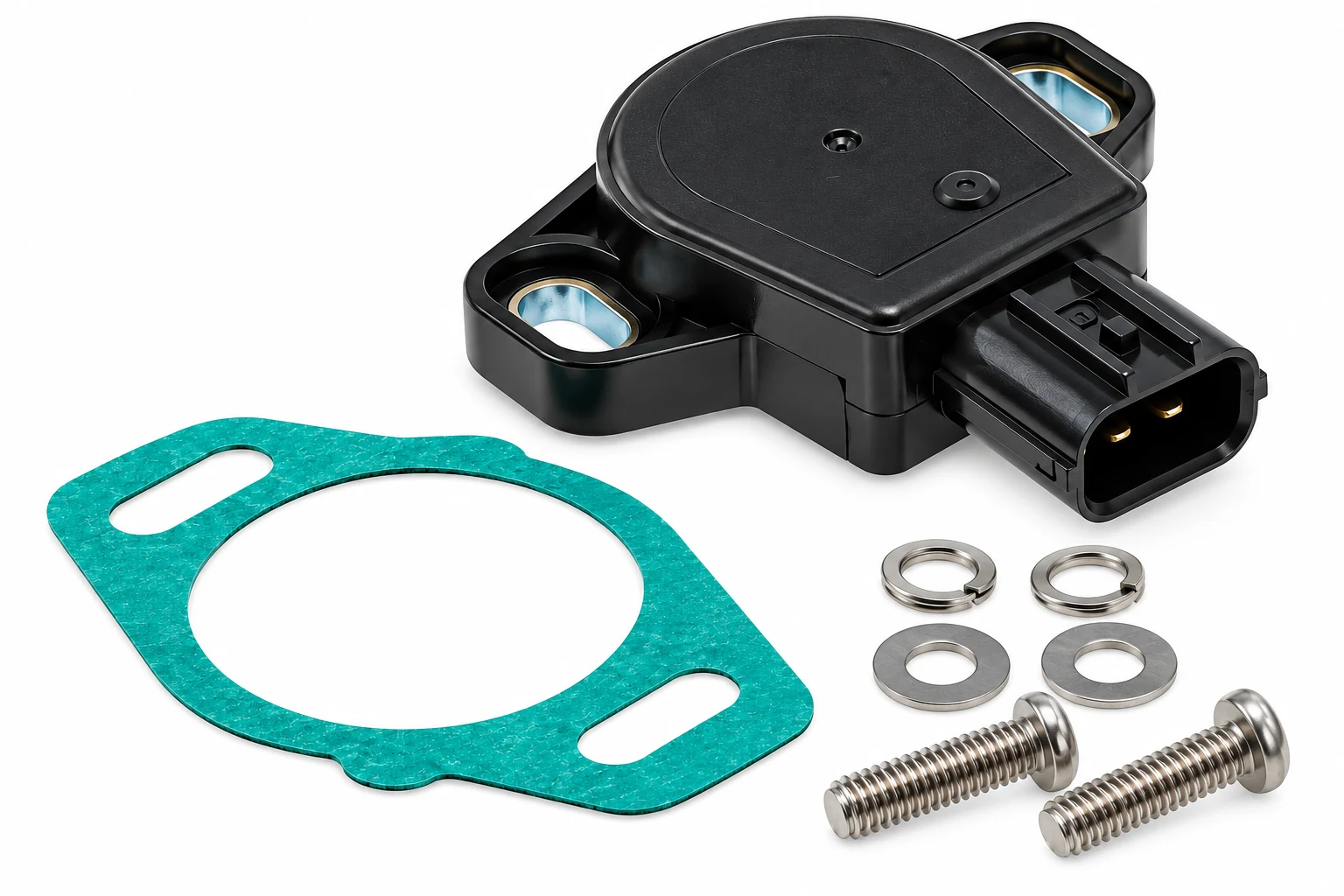
Mobile Throttle Position Sensor Diagnostics in Daytona Beach
A throttle-position-related trouble code does not automatically mean the throttle position sensor itself has failed.
Depending on the vehicle and symptoms, diagnosis can include checking:
- Throttle Position Sensor 1
- Throttle Position Sensor 2
- Closed-throttle signal
- Part-throttle response
- Wide-open-throttle response
- Signal voltage
- 5-volt reference
- Sensor ground
- Signal circuit
- Connector condition
- Wiring harness
- Commanded throttle position
- Actual throttle position
- Accelerator-pedal position
- Throttle actuator operation
- MAF data
- MAP data
- Engine RPM
- Fuel trims
- Battery voltage
- Related trouble codes
- Freeze-frame data
The objective is to determine whether the throttle position sensor is truly inaccurate or whether another component in the throttle-control system is causing the unusual reading.
What Is a Throttle Position Sensor?
The throttle position sensor, commonly called the TPS, monitors the physical position of the throttle plate or throttle shaft.
Depending on vehicle design, the TPS may be:
- A separate sensor mounted on the throttle shaft
- Integrated into an electronic throttle body
- One of two redundant position sensors inside the throttle assembly
The sensor converts throttle movement into an electrical signal that the PCM can interpret.
What Does the Throttle Position Sensor Do?
The TPS provides the PCM with information about throttle opening.
That information may influence:
- Fuel injection
- Ignition timing
- Acceleration enrichment
- Deceleration strategy
- Transmission shifting
- Torque-converter operation
- Cruise control
- Traction control
- Electronic throttle control
- Engine-load calculation
A smooth, accurate throttle-position signal is therefore important for drivability.
TPS Sensor vs. Throttle Body
These are related but not always the same component.
Throttle Position Sensor
Measures throttle plate position.
Throttle Body
Physically controls airflow into the engine.
On older vehicles, the TPS may be separately replaceable.
On many modern drive-by-wire systems, the TPS is built into the throttle body and may not be serviced separately.
In those cases, an internal TPS failure can require replacement of the complete throttle-body assembly.
TPS Sensor vs. Accelerator Pedal Position Sensor
The throttle position sensor and accelerator pedal position sensor perform different jobs.
Accelerator Pedal Position Sensor
Measures how far the driver is pressing the accelerator pedal.
Throttle Position Sensor
Measures how far the throttle plate actually moved.
On an electronic throttle-control system, the PCM compares the two.
If the pedal requests more throttle but the actual throttle plate does not follow correctly, the problem may involve:
- Throttle body
- Throttle actuator
- TPS
- Wiring
If the pedal signal itself is incorrect, replacing the TPS will not solve the problem.
TPS Sensor vs. MAP Sensor
The TPS measures throttle angle.
The MAP sensor measures intake-manifold pressure.
As the throttle opens, MAP usually changes in a predictable way.
The PCM can compare:
- Throttle angle
- Manifold pressure
- RPM
to determine whether the engine data makes sense.
A MAP problem can therefore create symptoms that overlap with TPS faults, but the two sensors should be diagnosed separately.
TPS Sensor vs. MAF Sensor
The TPS measures throttle position.
The MAF sensor measures the mass of air entering the engine.
A vehicle can have:
- Correct throttle movement with incorrect airflow measurement
- Incorrect throttle-position data with a perfectly good MAF sensor
Comparing both signals can help identify which input is implausible.
Mechanical Throttle TPS
Older cable-operated throttle systems often use a separate TPS attached directly to the throttle shaft.
As the driver presses the accelerator pedal:
- The cable rotates the throttle shaft.
- The throttle plate opens.
- The TPS rotates with the shaft.
- The sensor voltage changes.
- The PCM interprets the throttle opening.
These sensors are often separately replaceable.
Electronic Throttle TPS
Modern electronic throttle bodies typically contain one or more internal throttle-position sensors.
The system may include:
- Electric throttle actuator motor
- TPS 1
- TPS 2
- Throttle plate
- Throttle shaft
- Internal electronics
The sensors provide feedback so the PCM knows whether the throttle plate actually reached the commanded position.
Why Modern Throttle Bodies Use Two Position Sensors
Electronic throttle control is safety-critical.
For that reason, many systems use two position signals that the PCM continuously compares.
Depending on design:
- One signal may rise as the throttle opens
- The other may fall
- Both may rise at different rates
The exact relationship varies.
The important point is that the signals must remain within an expected correlation.
TPS 1 and TPS 2
On a dual-sensor system, scan data may display:
- Throttle Position Sensor 1
- Throttle Position Sensor 2
The two values should follow the programmed relationship throughout throttle movement.
A disagreement can indicate:
- Internal sensor failure
- Wiring problem
- Connector issue
- Throttle-body problem
How a Throttle Position Sensor Works
Traditional TPS designs commonly use a potentiometer.
A potentiometer contains a resistive track and moving contact.
As the throttle shaft rotates:
- The internal contact moves
- Electrical resistance changes
- Output voltage changes
The PCM reads that voltage as throttle position.
Potentiometer-Type TPS
A typical three-wire potentiometer TPS may use:
- 5-volt reference
- Sensor ground
- Signal wire
The signal generally changes progressively from closed throttle toward wide-open throttle.
Exact voltages vary by vehicle.
Hall-Effect Throttle Position Sensor
Some modern sensors use Hall-effect technology instead of a mechanical resistive track.
Hall-effect sensors can provide position information without the same type of sliding electrical contact used by older potentiometers.
The diagnostic principles still include checking:
- Reference voltage
- Ground
- Signal plausibility
- Smooth response
but the exact test method depends on design.
TPS 5-Volt Reference
Many throttle-position sensors operate from a regulated:
5-volt reference
supplied by the PCM.
If the reference voltage is missing, the TPS cannot produce a correct signal.
Possible causes include:
- Open reference wire
- Shorted 5-volt circuit
- Another sensor pulling down a shared reference
- PCM problem
Replacing the TPS will not repair a missing reference circuit.
Shared 5-Volt Reference
The TPS may share its 5-volt supply with other sensors.
Depending on the vehicle, these may include:
- MAP sensor
- Fuel pressure sensor
- AC pressure sensor
- Accelerator pedal sensor
A shorted sensor elsewhere can pull the shared voltage down and make the TPS appear defective.
The reference circuit should therefore be tested before replacing the sensor.
TPS Ground
The sensor requires a stable low-reference or ground circuit.
A poor ground can cause:
- Incorrect signal voltage
- Intermittent throttle reading
- High or low input codes
- Correlation faults
Voltage-drop testing may reveal a ground problem that a simple continuity test misses.
TPS Signal Wire
The signal wire carries the throttle-position information to the PCM.
Possible faults include:
- Open circuit
- Short to ground
- Short to voltage
- High resistance
- Intermittent connection
The signal should change smoothly as the throttle moves.
Throttle Position Sensor Connector
The TPS connector should be inspected for:
- Corrosion
- Bent terminals
- Loose pins
- Spread terminals
- Broken lock
- Water intrusion
- Oil contamination
- Heat damage
A new sensor cannot correct poor terminal contact.
TPS Wiring Harness
Harness damage can result from:
- Engine vibration
- Chafing
- Heat
- Oil exposure
- Previous repairs
- Rodent damage
An intermittent wire can create the same symptoms as an internal TPS dead spot.
Signs of a Bad Throttle Position Sensor
Possible symptoms include:
- Check-engine light
- Hesitation
- Surging
- Poor acceleration
- Erratic throttle response
- Rough idle
- High idle
- Stalling
- Reduced Engine Power message
- Electronic throttle-control warning
- Abnormal transmission shifting
- Throttle-position trouble codes
These symptoms overlap with many other faults.
Testing should establish that the sensor signal itself is incorrect.
TPS and Hesitation
A TPS with a worn or damaged portion of its internal sensing range can momentarily send an incorrect signal as the throttle passes through a particular angle.
Possible symptoms include:
- Hesitation
- Flat spot
- Sudden stumble
This is often described as a:
dead spot
in the TPS signal.
TPS Dead Spot
A dead spot is a section of throttle travel where the output:
- Drops suddenly
- Jumps
- Becomes intermittent
- Stops changing normally
A sensor can work correctly at idle and wide-open throttle yet still fail in the middle of its range.
This is why a full signal sweep is more useful than checking one voltage value.
TPS and Surging
If the TPS signal jumps unexpectedly while the throttle plate is physically steady, the PCM may interpret that as a sudden change in driver demand or engine load.
This can contribute to:
- Surging
- Erratic fueling
- Unstable transmission behavior
The signal should be monitored continuously.
TPS and Poor Acceleration
An inaccurate throttle-position signal can affect:
- Fueling
- Ignition timing
- Electronic throttle strategy
But poor acceleration can also result from:
- Low fuel pressure
- MAF fault
- MAP fault
- Ignition misfire
- Restricted exhaust
The TPS should not be replaced based only on lack of power.
TPS and Rough Idle
A TPS that falsely indicates the throttle is partly open when it is actually closed can affect idle-control strategy.
However, rough idle is more commonly associated with:
- Vacuum leaks
- Ignition misfires
- Fuel injectors
- Dirty throttle body
- Compression problems
The sensor reading should support the diagnosis.
TPS and High Idle
A high idle can occur if the PCM receives incorrect closed-throttle information.
However, possible causes also include:
- Vacuum leak
- Throttle plate sticking
- Incorrect throttle adaptation
- Electronic throttle actuator fault
Actual and commanded throttle data should be compared.
TPS and Stalling
A severely erratic TPS signal can affect fuel or throttle-control strategy.
But stalling can also result from:
- Crankshaft sensor
- Fuel pump
- Charging-system fault
- Vacuum leak
The TPS signal should be captured during the symptom if possible.
TPS and Hard Starting
The TPS can influence startup strategy, but it is usually not the first component suspected in a conventional crank-no-start or hard-start complaint.
Other causes can include:
- Fuel pressure
- Coolant temperature
- Crankshaft signal
- Battery voltage
Testing should determine whether the throttle-position signal is implausible during startup.
TPS and Poor Fuel Economy
An inaccurate throttle-position signal can alter load calculations or transmission behavior.
However, poor fuel economy has many causes.
The TPS should not be replaced based on fuel consumption alone.
TPS and Transmission Shifting
On some vehicles, throttle-position information is used for:
- Shift timing
- Line-pressure strategy
- Torque-converter operation
A faulty TPS on certain older systems can contribute to:
- Harsh shifts
- Delayed shifts
- Incorrect shift timing
Transmission symptoms should still be diagnosed carefully because many other inputs influence shift strategy.
TPS and Automatic Transmission Behavior
If the transmission controller sees an implausible throttle position, it may miscalculate driver demand.
Possible effects can include:
- Holding gears too long
- Early shifting
- Harsh shifting
This is more common on systems that rely heavily on throttle-position data.
TPS and Cruise Control
Electronic throttle systems use throttle-position feedback during cruise-control operation.
A TPS fault may cause the PCM to:
- Disable cruise control
- Enter reduced-power mode
Cruise-control failure alone does not prove a bad TPS.
TPS and Traction Control
The PCM may reduce engine torque during traction-control events by controlling throttle angle.
An unreliable throttle-position signal can interfere with that strategy.
This can lead to:
- Traction-control warnings
- Electronic throttle-control faults
The underlying code should be diagnosed.
TPS and Reduced Engine Power
If the PCM detects that throttle-position signals do not agree with one another or with the commanded throttle angle, it may intentionally reduce engine power.
Possible behavior includes:
- Limited throttle opening
- Slow acceleration
- RPM limitation
The reduced-power condition is a safety response.
It does not automatically mean the TPS itself is the root cause.
TPS and Electronic Throttle Control Warning
An ETC warning can be caused by:
- TPS failure
- Throttle actuator motor
- Accelerator pedal sensor
- Wiring
- Low system voltage
- PCM fault
The entire electronic throttle system should be evaluated.
TPS and Accelerator Pedal Correlation
On drive-by-wire systems, the PCM compares:
- Accelerator pedal position
- Commanded throttle position
- Actual throttle position
If pedal data changes normally but actual throttle-position feedback is erratic, the throttle-body/TPS side becomes more suspicious.
If pedal data itself is incorrect, replacing the TPS may not fix the problem.
TPS and Commanded Throttle
Commanded throttle is what the PCM is asking the actuator to do.
Actual throttle position is what the TPS reports.
If:
- Commanded angle changes normally
- Actual angle does not follow
possible causes include:
- Throttle actuator problem
- Sticking plate
- TPS feedback issue
The distinction is important because the TPS only reports movement; it does not drive the throttle motor.
TPS and Throttle Actuator Motor
The throttle actuator motor physically moves the plate.
The TPS reports where the plate is.
A failed motor can cause the plate not to move even though the TPS correctly reports its actual position.
Replacing a good TPS will not repair a failed actuator motor.
TPS and Dirty Throttle Body
Carbon buildup can cause the throttle plate to:
- Stick
- Move slowly
- Fail to return smoothly
The TPS may accurately report that abnormal movement.
In such a case, the sensor is not necessarily faulty.
The throttle body may need cleaning or mechanical repair.
TPS and Vacuum Leak
A vacuum leak can cause:
- High idle
- Rough idle
- Lean fuel trims
without changing the actual throttle-position signal.
The PCM may command a different throttle angle in response to the leak.
TPS data should therefore be interpreted together with airflow and fuel-trim information.
TPS and MAF Sensor
If the throttle opens but MAF airflow does not increase as expected, possible causes include:
- MAF problem
- Intake restriction
- Throttle plate not actually opening
The TPS indicates position, not actual airflow volume.
TPS and MAP Sensor
As the throttle opens on a naturally aspirated gasoline engine:
- Manifold pressure generally rises toward atmospheric pressure
If TPS indicates a large throttle opening but MAP pressure does not respond appropriately, the system requires further investigation.
Possible causes include:
- MAP problem
- Intake restriction
- Mechanical throttle problem
TPS and Fuel Pressure
A vehicle with correct throttle-position data but inadequate fuel pressure can hesitate or lose power.
The TPS cannot compensate for insufficient fuel delivery.
Fuel pressure should be checked when symptoms and data suggest a supply problem.
TPS and Ignition Misfire
Misfires from:
- Spark plugs
- Coils
- Injectors
- Compression
can cause hesitation and poor acceleration that feel like throttle problems.
A smooth TPS signal makes the sensor less likely to be the cause.
TPS and Battery Voltage
Electronic throttle systems depend on stable voltage.
Low battery or charging voltage can create:
- Multiple sensor codes
- ETC warnings
- Reduced-power operation
Electrical system health should be considered when several throttle-related faults appear at once.
Throttle Position Sensor Trouble Codes
Common throttle-position-related codes can include:
- P0120
- P0121
- P0122
- P0123
- P0124
- P0220
- P0221
- P0222
- P0223
- P0224
- P2135
Exact definitions vary by vehicle.
P0120 Throttle Position Sensor Circuit
P0120 generally indicates a problem involving a throttle-position circuit.
Possible causes include:
- TPS
- Wiring
- Connector
- Reference voltage
- Ground
The circuit should be tested before sensor replacement.
P0121 TPS Range/Performance
P0121 commonly indicates that the throttle-position signal does not behave as expected.
Possible causes include:
- TPS dead spot
- Incorrect sensor adjustment
- Sticking throttle plate
- Wiring problem
- Correlation issue
A range/performance code often requires testing the signal through the full throttle range.
P0122 TPS Circuit Low
P0122 generally indicates lower-than-expected signal voltage.
Possible causes include:
- Signal short to ground
- Missing 5-volt reference
- Sensor fault
- Wiring issue
A low signal does not automatically mean the sensor is defective.
P0123 TPS Circuit High
P0123 generally indicates a higher-than-expected signal.
Possible causes include:
- Signal short to voltage
- Open sensor ground
- TPS failure
- Connector problem
The electrical circuit should be verified.
P0124 TPS Intermittent
P0124 typically indicates an intermittent throttle-position circuit.
Possible causes include:
- Internal TPS wear
- Loose connector
- Broken wire
- Harness movement
An intermittent sweep test can be especially useful.
P0220 Throttle Position Sensor B Circuit
P0220 commonly refers to another throttle-position circuit on systems with multiple sensor signals.
The exact sensor designation varies by manufacturer.
The correct circuit should be identified before replacement.
P0221 TPS B Range/Performance
This generally indicates an implausible signal from another throttle-position channel.
Possible causes include:
- Integrated TPS failure
- Wiring
- Connector
- Mechanical throttle problem
Correlation with the other TPS signal is important.
P0222 TPS B Circuit Low
A low-input condition can result from:
- Short to ground
- Open reference
- Sensor failure
Circuit testing is required.
P0223 TPS B Circuit High
A high-input fault can result from:
- Short to voltage
- Ground problem
- Internal sensor failure
Again, the sensor is only one possible cause.
P2135 Throttle Position Sensor Correlation
P2135 commonly indicates that two throttle-position signals no longer agree as expected.
This is particularly important on electronic throttle-control systems.
Possible causes include:
- Internal throttle-body sensor failure
- Connector problem
- Wiring fault
- Shared reference issue
Because many modern TPS units are integrated into the throttle body, replacement of the entire throttle-body assembly may be required if internal sensor failure is confirmed.
TPS Voltage at Closed Throttle
On many traditional analog TPS designs, the closed-throttle signal is a relatively low voltage.
A commonly encountered general pattern might be around:
- Roughly 0.5 volt closed
but the correct specification varies by vehicle.
The actual manufacturer specification should be used.
TPS Voltage at Wide-Open Throttle
Traditional analog TPS output often rises toward the upper end of the 5-volt range at wide-open throttle.
A general example might be approximately:
- 4 to 4.5 volts
but the exact value depends on design.
The smoothness of the sweep is often more important than hitting one generic number.
TPS Signal Sweep
A proper TPS sweep test evaluates the entire throttle range.
The output should normally change:
- Smoothly
- Predictably
- Without sudden dropouts
A sensor can pass a closed-throttle voltage test yet still have a worn area in the middle of its travel.
Testing TPS With a Multimeter
A digital multimeter can be useful for checking:
- 5-volt reference
- Ground
- Signal voltage
- Resistance on certain disconnected sensors
For an analog TPS, slowly opening the throttle while monitoring the signal can reveal obvious dead spots.
However, a basic digital meter may miss very brief glitches.
Testing TPS With an Oscilloscope
An oscilloscope can display the throttle-position signal continuously.
This can reveal:
- Short dropouts
- Spikes
- Dead spots
- Electrical noise
- Intermittent connection
Oscilloscope testing is especially useful when hesitation occurs only at a narrow throttle angle.
Testing TPS With a Scan Tool
A scan tool may display throttle position as:
- Percentage
- Voltage
- Angle
The data should change smoothly as the accelerator is operated.
On electronic throttle systems, useful parameters can include:
- APP 1
- APP 2
- Commanded throttle
- Actual throttle
- TPS 1
- TPS 2
Comparing these values can narrow the fault considerably.
TPS Percentage on Scan Tool
Throttle percentage does not always start at:
- 0%
or reach exactly:
- 100%
The PCM may scale or normalize the data differently.
A nonzero idle percentage by itself does not prove the TPS is misadjusted.
Vehicle-specific data should be interpreted in context.
Throttle Position at Idle
On cable-operated systems, the TPS should indicate the expected closed-throttle range when the plate rests against its proper stop.
On electronic systems, the PCM may intentionally hold the throttle slightly open at idle.
Therefore, idle TPS percentage alone should not be used to condemn the sensor.
TPS Wide-Open-Throttle Test
As the throttle opens fully, the TPS should reach the expected upper range without:
- Flat spots
- Dropouts
- Sudden reversals
The exact percentage or voltage depends on the vehicle.
TPS Resistance Test
Some older potentiometer-type sensors can be checked for resistance.
The resistance should generally change smoothly as the shaft moves.
However, many modern electronic sensors should not be diagnosed using a generic resistance test.
The correct method should match sensor design.
TPS Dead Spot Testing
A dead spot may only occur at a particular throttle angle.
A useful test is to move the throttle slowly while watching:
- Voltage
- Percentage
- Oscilloscope waveform
If the signal suddenly falls or jumps while the plate moves smoothly, the TPS or its circuit becomes more suspicious.
Intermittent TPS Failure
Intermittent failures can occur because of:
- Worn resistive track
- Internal contact problem
- Vibration
- Heat
- Wiring movement
The vehicle may run normally most of the time and hesitate only under a specific pedal position.
Heat-Related TPS Failure
Some electronic components can become unstable as temperature increases.
If a TPS-related fault appears only after the engine compartment becomes hot, comparing sensor behavior:
- Cold
- Hot
can help identify the problem.
Wiring and connectors can also become heat-sensitive.
TPS Connector Wiggle Test
If an intermittent fault is suspected, carefully moving the connector and harness while monitoring live TPS data can reveal:
- Voltage spikes
- Sudden signal loss
- Correlation faults
The wiring should not be pulled aggressively.
TPS Adjustment
Some older throttle position sensors are adjustable.
Adjustment can involve rotating the sensor slightly before tightening its screws.
The closed-throttle voltage must then be set according to the manufacturer specification.
Modern integrated TPS systems are generally not manually adjustable.
Adjustable TPS
On an adjustable sensor, incorrect installation position can cause:
- High idle signal
- Incorrect closed-throttle recognition
- Poor shift behavior
The sensor should be installed and adjusted according to vehicle-specific specifications.
Nonadjustable TPS
Many sensors are indexed to the throttle shaft and cannot be manually calibrated.
If the signal remains incorrect despite proper installation and wiring, replacement may be required.
TPS Mounting Screws
TPS sensors may be retained with:
- Small screws
- Torx fasteners
- Tamper-resistant fasteners
These components can be delicate.
Overtightening can:
- Crack the sensor housing
- Strip throttle-body threads
TPS Shaft Engagement
A separate TPS must correctly engage the throttle shaft.
If installed incorrectly, the sensor can:
- Bind
- Read incorrectly
- Be damaged during tightening
The position of the internal tang or slot should be matched carefully.
Throttle Position Sensor Replacement
Once diagnostics confirm that a separately serviceable throttle position sensor is defective, replacement generally includes:
- Verify the complaint and trouble codes.
- Review freeze-frame information.
- Check TPS data at closed throttle.
- Monitor the signal through the complete throttle range.
- Look for dead spots or dropouts.
- Verify the 5-volt reference.
- Verify sensor ground.
- Check the signal circuit.
- Inspect the connector and harness.
- Compare TPS data with accelerator-pedal input where applicable.
- Compare actual and commanded throttle position on electronic systems.
- Turn the ignition off.
- Disconnect the electrical connector.
- Remove intake components required for access if necessary.
- Mark the position of an adjustable sensor where appropriate.
- Remove the TPS mounting screws.
- Remove the sensor carefully from the throttle shaft.
- Inspect the shaft and mounting area.
- Compare the replacement sensor with the original.
- Align the new sensor correctly with the throttle shaft.
- Install the retaining screws.
- Adjust the sensor where required.
- Reconnect the electrical connector.
- Turn the ignition on.
- Verify closed-throttle signal.
- Check signal through the full throttle range.
- Perform relearn or adaptation where required.
- Start the engine.
- Verify idle operation.
- Clear applicable codes.
- Road-test the vehicle.
- Confirm the original symptom does not return.
The exact procedure depends on whether the sensor is separately serviceable or integrated into the throttle body.
TPS Integrated Into Throttle Body
On many modern vehicles, the TPS is not sold or serviced separately.
If diagnostics confirm failure of an internal position sensor, the appropriate repair may be:
complete throttle-body replacement
This is because the sensor, motor, gears, and throttle assembly are designed and calibrated as one unit.
Can You Replace Just the TPS on an Electronic Throttle Body?
Sometimes no.
Many drive-by-wire throttle bodies use sealed or nonserviceable internal position sensors.
Attempting to replace or modify an internal TPS not designed for separate service can compromise:
- Calibration
- Safety
- Reliability
The service information should determine whether the sensor is replaceable separately.
New TPS Requires Adjustment
Older adjustable sensors may require:
- Closed-throttle voltage setting
- Idle switch confirmation where applicable
A sensor that is physically installed but not correctly adjusted can still produce a code or drivability problem.
TPS Relearn
Some vehicles may require a relearn after:
- TPS replacement
- Throttle-body replacement
- Battery disconnection
The procedure may involve:
- Ignition-key sequence
- Idle period
- Scan tool
The exact method varies.
Does a TPS Need Programming?
A conventional separately replaceable TPS usually does not require programming.
However, certain systems may require:
- Throttle relearn
- Idle relearn
- Adaptation
Programming and relearning are different procedures.
New TPS but Code Returns
If a TPS code returns after replacement, possible causes include:
- Wiring problem
- Connector fault
- Missing reference voltage
- Poor ground
- Incorrect sensor
- Improper adjustment
- Throttle-body mechanical problem
- PCM issue
Another sensor should not automatically be installed.
New TPS but P0121 Returns
A recurring range/performance code may indicate:
- Incorrect adjustment
- Signal dead spot
- Throttle plate sticking
- Wiring problem
- Correlation issue
The signal should be checked through the entire range.
New TPS but P0122 Returns
A recurring low-input code can indicate:
- Reference-voltage problem
- Signal short to ground
- Poor connector
- Incorrect sensor
Circuit testing should continue.
New TPS but P0123 Returns
A recurring high-input code can indicate:
- Signal short to voltage
- Open ground
- Connector issue
- Incorrect adjustment
The new sensor should not automatically be blamed.
New TPS but Car Still Hesitates
Possible causes include:
- MAF sensor
- MAP sensor
- Fuel pressure
- Ignition misfire
- Vacuum leak
- Throttle-body sticking
A smooth TPS signal after replacement indicates another system may be responsible.
New TPS but Reduced Power Remains
On an electronic throttle-control vehicle, reduced power can remain because of:
- Accelerator pedal sensor
- Throttle actuator motor
- Wiring
- TPS correlation problem in the integrated throttle body
- Low battery voltage
The full ETC system should be rechecked.
OEM vs. Aftermarket TPS
Throttle position is a precision input.
The PCM expects the sensor to produce the correct:
- Closed-throttle value
- Full-throttle value
- Signal progression
- Correlation
A poor-quality sensor may physically fit but produce incorrect calibration.
A quality replacement matched to the exact application is important.
Cheap TPS Sensor Problems
Low-quality sensors may cause:
- Incorrect closed-throttle voltage
- Dead spots
- Intermittent readings
- Recurring P0121/P0122/P0123 codes
Part quality can be especially important on older adjustable sensors.
Used TPS Sensor
A used potentiometer-type TPS may already have wear on its internal resistive track.
Its remaining service life is unknown.
A quality new sensor is generally more predictable.
Throttle Position Sensor Replacement Cost
TPS replacement cost depends on:
- Vehicle year, make, and model
- Separate vs. integrated sensor
- Throttle-body access
- Adjustment requirements
- Wiring repair
- Diagnostic time
- Relearn requirements
A separately replaceable TPS can be a relatively straightforward repair.
An integrated TPS failure can require replacement of the entire electronic throttle-body assembly.
Call Jimmy’s Mobile Care at (386) 308-2509 with your vehicle information and symptoms so we can determine what type of throttle-position system your vehicle uses and what testing is appropriate.
Why Diagnose a Throttle Position Sensor Before Replacing It?
Throttle-position complaints can be caused by several components in the same control system.
Is the 5-Volt Reference Correct?
A new sensor cannot repair a missing reference supply.
Is Sensor Ground Good?
Ground resistance can distort the signal.
Does the TPS Signal Sweep Smoothly?
A dead spot can reveal internal sensor wear.
Does the Signal Match Actual Throttle Movement?
An abnormal signal with smooth physical movement makes the sensor or circuit more suspicious.
Does the Accelerator Pedal Signal Make Sense?
A bad pedal sensor can create poor response while the TPS remains accurate.
Does Commanded Throttle Match Actual Throttle?
A failed actuator motor can prevent movement while the TPS accurately reports the plate’s actual position.
Is the Throttle Plate Sticking?
Carbon or mechanical binding can create a throttle-control fault without TPS failure.
Are MAF and MAP Data Plausible?
Airflow and manifold-pressure data help verify whether throttle-position information makes sense.
Is the Wiring Intermittent?
A damaged harness can imitate a sensor dead spot.
Is the TPS Separately Replaceable?
On many modern vehicles, internal TPS failure requires complete throttle-body replacement.
Testing these areas helps prevent unnecessary sensor replacement and identifies the actual throttle-control fault.
Mobile Throttle Position Sensor Diagnostics in Daytona Beach
Jimmy’s Mobile Care provides mobile car throttle position sensor diagnostics in Daytona Beach for vehicles experiencing:
- P0120
- P0121
- P0122
- P0123
- P0124
- P0220
- P0221
- P0222
- P0223
- P0224
- P2135
- Hesitation
- Surging
- Poor throttle response
- High or rough idle
- Reduced Engine Power warning
- Electronic throttle-control warning
- Suspected TPS wiring problems
- Intermittent throttle-position readings
We evaluate TPS signal quality, reference voltage, ground, wiring, signal sweep, throttle movement, pedal inputs, and throttle-system correlation before determining whether the sensor itself needs replacement.
Mobile Throttle Position Sensor Replacement in Daytona Beach
When diagnostics confirm a defective separately serviceable TPS and the repair is appropriate for mobile service, Jimmy’s Mobile Care can replace many throttle position sensors at your Daytona Beach location.
After replacement, we can verify:
- Correct sensor installation
- Proper shaft engagement
- Correct closed-throttle reading
- Smooth signal sweep
- Proper wide-open-throttle response
- Secure electrical connection
- Required adjustment
- Required relearn or adaptation
- No immediate return of the original fault
If the TPS is integrated into the electronic throttle body, we can determine whether the complete throttle-body assembly is the appropriate repair.
If the actual fault is an accelerator-pedal sensor, throttle actuator, damaged wiring, vacuum leak, MAF or MAP problem, or PCM issue, that condition must be repaired instead of unnecessarily replacing the TPS.
Schedule Car Throttle Position Sensor Diagnostics & Replacement in Daytona Beach
A P0121 code, hesitation, reduced-power message, unstable throttle response, or erratic TPS reading does not automatically mean the throttle position sensor needs replacement.
The problem may be a missing 5-volt reference, poor ground, connector fault, wiring damage, throttle-plate sticking, accelerator-pedal sensor fault, throttle actuator problem, or another airflow-control issue.
Jimmy’s Mobile Care tests the throttle-position sensor through its full operating range and compares its signal with the rest of the throttle-control system before replacement so the part is replaced only when the diagnosis supports it.
Call Jimmy’s Mobile Care at (386) 308-2509 to schedule car throttle position sensor diagnostics and replacement in Daytona Beach, FL. Call today and we'll come to your location.